A data center power solution is the complete electrical backbone protecting IT operations: utility switchgear, standby generators, UPS systems, and battery storage arranged in a redundancy topology (N+1, 2N, or 2N+1) so that no single equipment failure interrupts server uptime.
Resilient Power Architectures for Enterprise Data Centers
From single-server rooms to multi-megawatt colocation halls, we design UPS, generator, and battery storage architectures matched to your target Tier classification and uptime SLA.
Tier-Aligned Redundancy Engineering
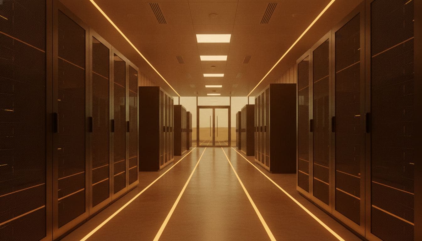
What is a data center power solution?
A data center power solution is the complete electrical backbone protecting IT operations: utility switchgear, standby generators, UPS systems, and battery storage arranged in a redundancy topology (N+1, 2N, or 2N+1) so that no single equipment failure interrupts server uptime.
Balancing Uptime, Cost, and Facility Constraints
Facility teams are frequently asked to increase redundancy without a matching increase in floor space, budget, or lead time. Over-specifying a Tier IV design for a Tier II workload wastes capital; under-specifying redundancy risks costly outages and SLA penalties.
We start from your actual IT load, growth roadmap, and contractual uptime commitments, then work backward to the minimum viable redundancy architecture, avoiding both stranded capacity and single points of failure.
System Architecture
- Utility Feed + Standby Generator
- Automatic Transfer Switch (ATS)
- UPS Modules (N+1 / 2N)
- Battery Strings (VRLA or Lithium)
- Power Distribution Units (PDU) to Racks
System Components
Modular UPS Systems
Scalable, hot-swappable UPS frames sized to grow with rack density.
For facilities expecting phased IT load growth.
Standby Generators
Diesel or gas gensets sized for full facility ride-through during extended outages.
For sites without dual utility feeds or with unreliable grid supply.
Battery Energy Storage (BESS)
Lithium-based bridging power between utility loss and generator start.
To reduce genset run-hours and shorten transfer gaps.
Ideal Applications
Colocation Halls
Multi-tenant facilities requiring contractual Tier III/IV uptime guarantees.
Enterprise Server Rooms
In-house IT rooms supporting ERP, finance, and core business systems.
Edge Data Centers
Smaller regional facilities requiring compact, high-density backup.
Telecom Central Offices
Switching facilities with strict continuous-power regulatory requirements.
Deployment Process
1. Assess
Audit existing switchgear, IT load schedules, and single-line diagrams.
2. Analyse
Determine target Tier classification and required redundancy level.
3. Design
Engineer the UPS, generator, and battery topology to match the SLA.
4. Configure
Specify equipment ratings, runtime targets, and monitoring architecture.
5. Procure and Deploy
Coordinate phased installation with minimal disruption to live IT loads.
6. Monitor and Optimise
Track battery health, run-hours, and transfer events post-commissioning.
Information We Need
- Current and projected IT load (kW)
- Existing utility feed configuration (single/dual)
- Target Tier classification (I-IV)
- Required battery runtime (minutes)
- Existing generator capacity, if any
- Facility floor space and weight constraints
Frequently Asked
Request a Data Center Power Assessment
Gletscher Energy will review your project requirements and recommend the next technical planning step.
- Engineering review of submitted details
- Initial feasibility assessment
- Direct consultation booking